Powerboard Connections
Fan Control Switch
The powerboard has a fan control switch that selects whether all fans are controlled by the motherboard or by the powerboard. Set the switch to the position you want:
MOBO FAN CTL Position
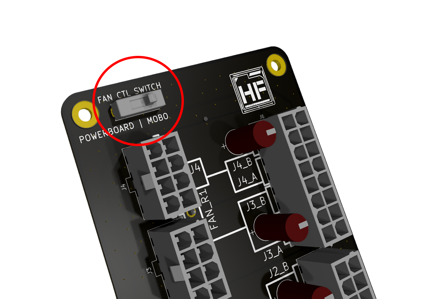
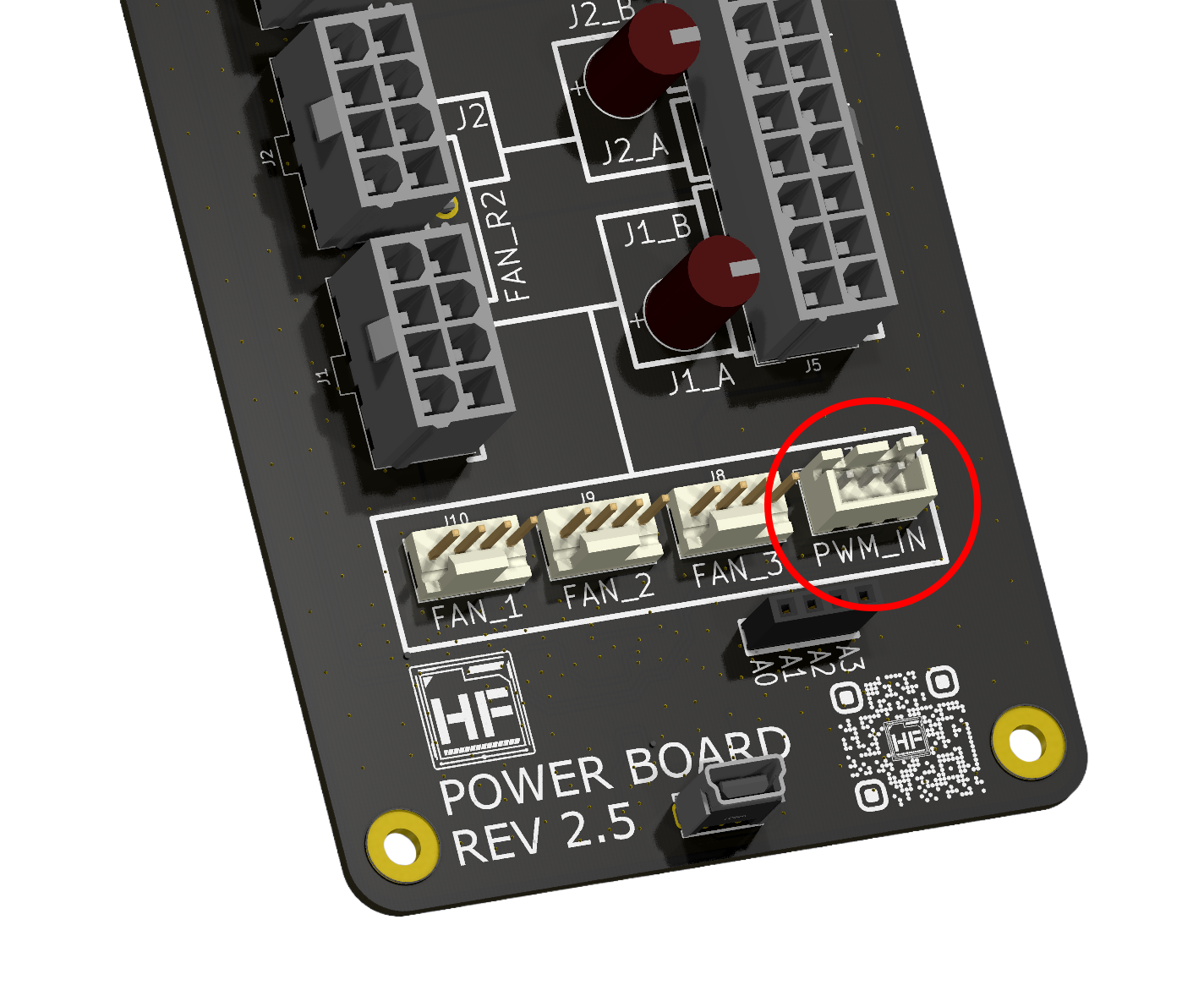
With the switch in this position, all fan headers will be controlled by the PWM_IN connector. This can be connected to a header on your motherboard or a dedicated fan controller. The USB connection is not required.
POWERBOARD FAN CTL Position
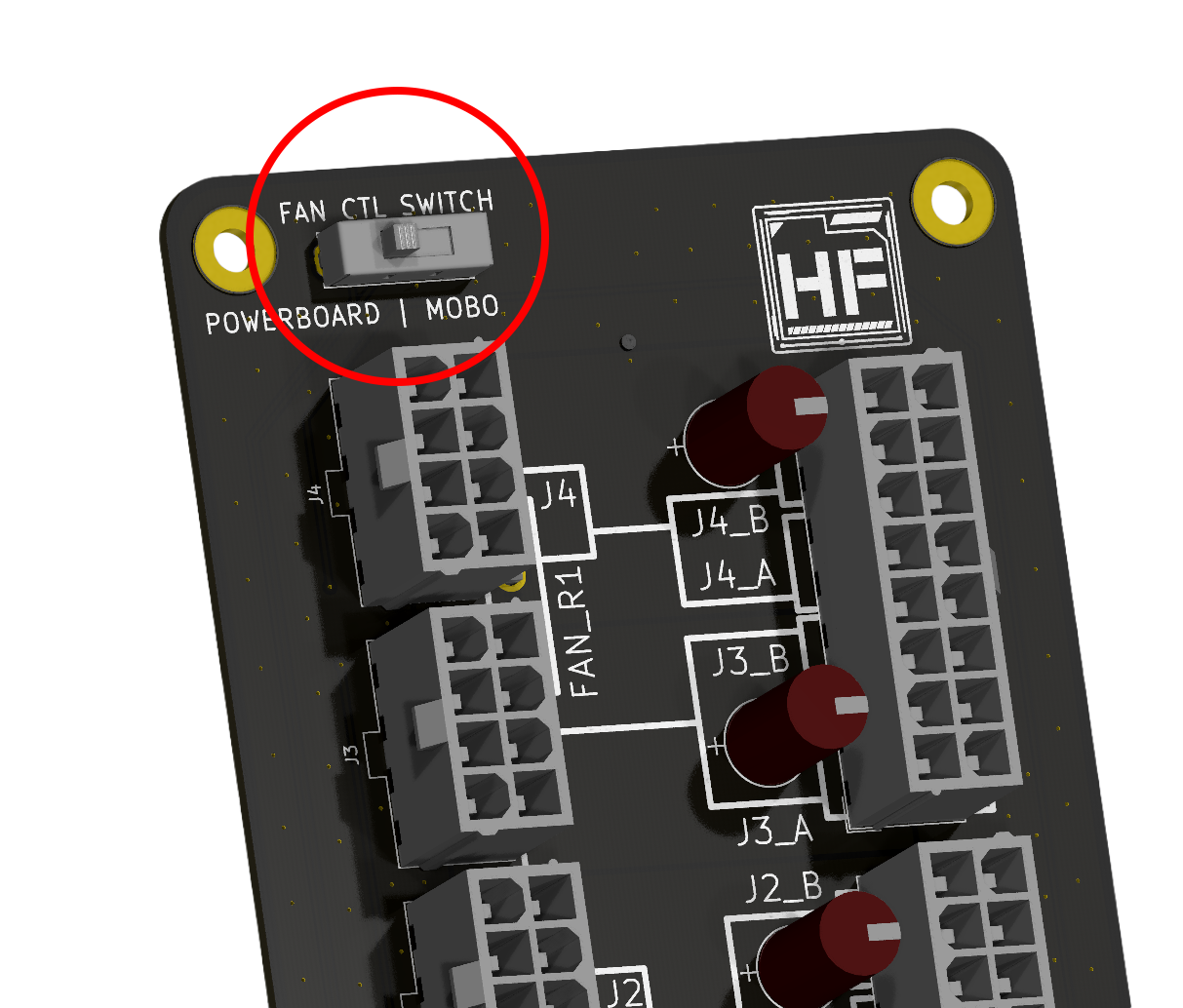
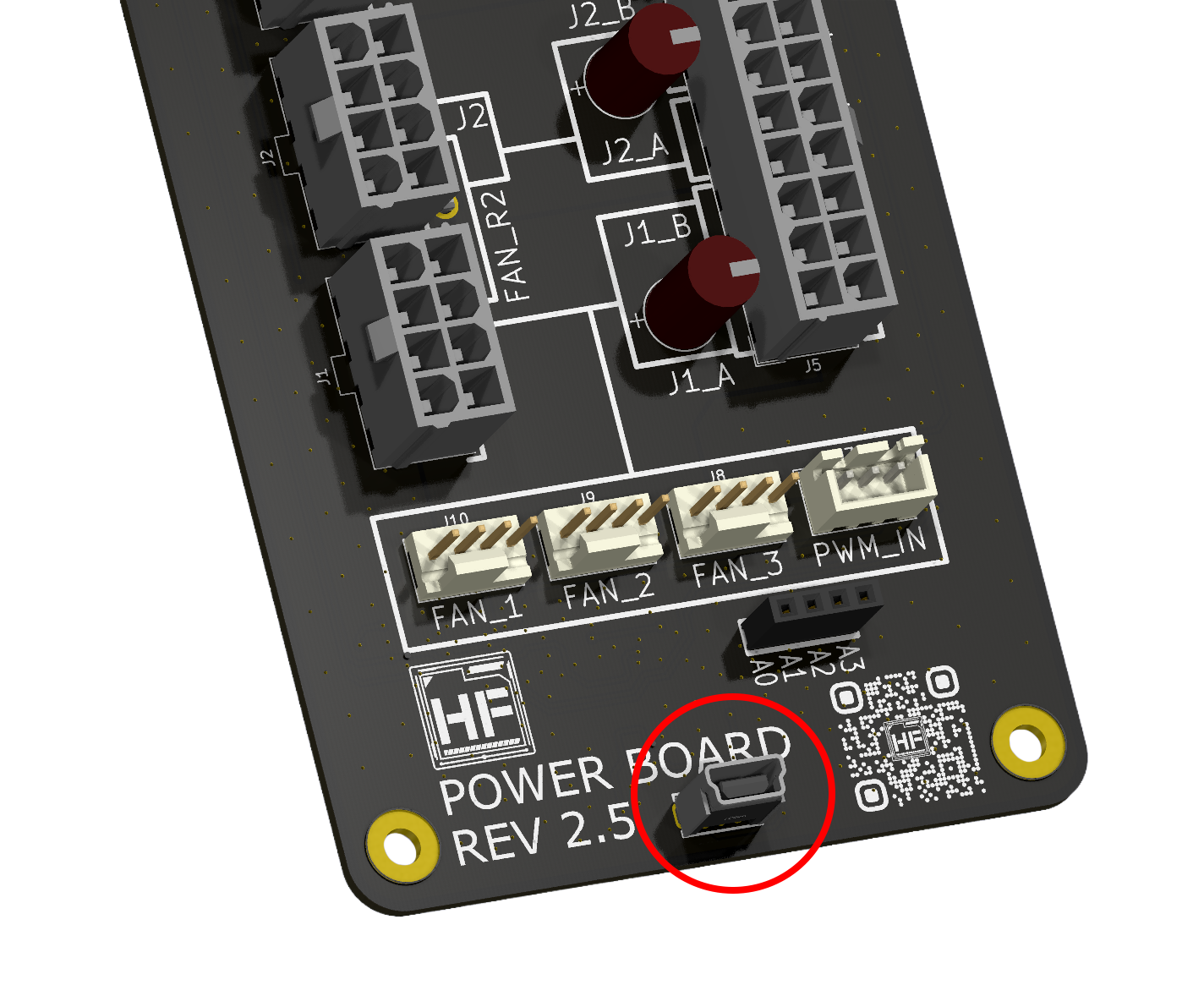
With the switch in this position, all fan headers will be controlled by the powerboard. A USB connection is required. With the Hako Foundry software, you're able to control each fan wall individually.
Fan Wall Control & RPM
Each fan wall is controlled as a group — all fans on a wall run at the same speed, not individually. Like any fan splitter, only one fan per wall reports RPM, so a failed fan in another position on that wall will not show up in HakoFoundry. Check the fans physically if you suspect a failure.
8-pin PCIe Connectors
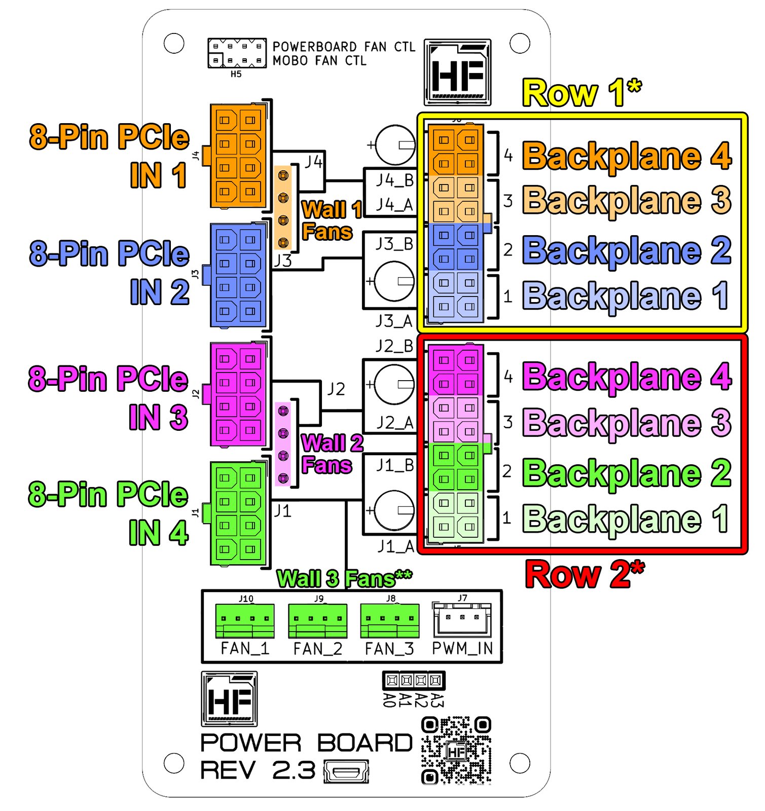
Each 8-Pin PCIe connector powers a specific set of hardware. If there is a set of hardware that is not being used in your configuration, connection is optional.
Connector Labels
The IN 1–4 labels are for ease of use; they map to the board's silkscreened J connectors shown on the diagram above — IN 1 = J4, IN 2 = J3, IN 3 = J2, IN 4 = J1 (the J numbers run opposite to the IN numbers).
8-Pin PCIe IN 1
- Row 1* Backplane 4
- Row 1* Backplane 3
- Fan wall 1
8-Pin PCIe IN 2
- Row 1* Backplane 2
- Row 1* Backplane 1
8-Pin PCIe IN 3
- Row 2* Backplane 4
- Row 2* Backplane 3
- Fan wall 2
8-Pin PCIe IN 4
- Row 2* Backplane 2
- Row 2* Backplane 1
- Fan wall 3**
Dual Powerboard Hako-Core Configuration
* Row 1 and Row 2 connections on the second powerboard are connected to Row 3 and Row 4
** The exposed Fan Wall 3 headers can be used for other fans if there is no fan wall 3 in your configuration
Mini-B USB to USB 2.0 Header
The Powerboard comes with a Mini-B USB to USB 2.0 Header that will connect to a USB 2.0 Header on your motherboard. This connection is required for individual fan wall control and power monitoring of drives. If these features are not used, the USB connection is optional.
USB 2.0 Header Connector Orientation
Take note of the empty pin on the connector and align them with the motherboard properly. Improper connection may cause damage to components.
PWM_IN to Fan Header
The Powerboard comes with a PWM_IN to Fan Header cable that will connect to a fan header on your motherboard. The connected motherboard fan header will control all fans connected to the powerboard. If fan control is not desired, leaving this unplugged will have the fans run at full speed.
PWM_IN and USB connected
Having both the PWM_IN and USB wires connected to the motherboard is OK. This configuration lets you change fan control between the motherboard and powerboard just by moving the switch.